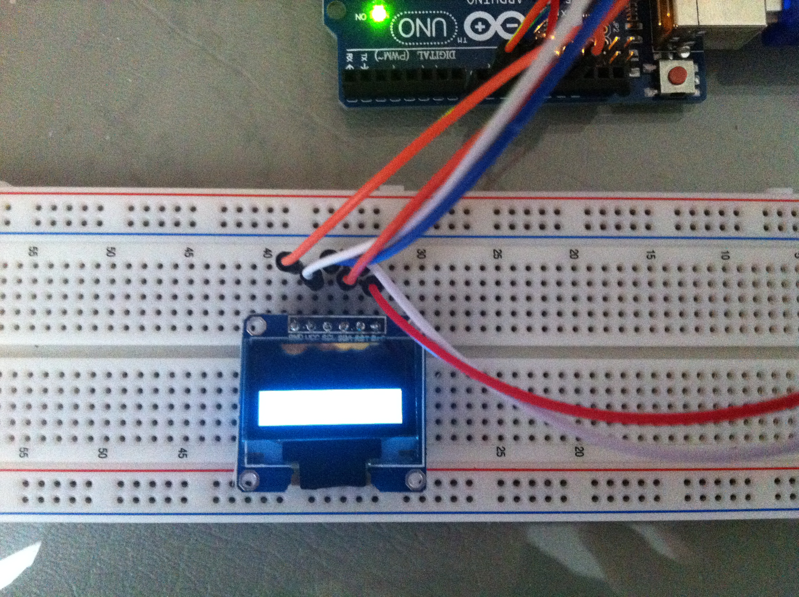
Arduino SSD1306 LED
A more simple version of Instructables example. For me, the most interesting part is the speeds to fill 1 byte ad fill 128 bytes in the same page are almost the same.
// SSD1306
// https://www.adafruit.com/datasheets/SSD1306.pdf
// 5v

#define PIN_DATA_COMMAND  (11)
#define PIN_RESET         (13)
#define PIN_SCL           (10)
#define PIN_SDA           (9)

void led_send(bool is_data, uint8_t data) {
  if (is_data) {
    digitalWrite(PIN_DATA_COMMAND, HIGH);
  } else {
    digitalWrite(PIN_DATA_COMMAND, LOW);
  }

  for (int i = 0; i < 8; ++i) {
    digitalWrite(PIN_SCL, LOW);

    if (data & 0x80) {
      digitalWrite(PIN_SDA, 1);
    } else {
      digitalWrite(PIN_SDA, 0);
    }

    digitalWrite(PIN_SCL, HIGH);

    data <<= 1;
  }
}

void led_send_data(uint8_t data) {
  led_send(true, data);
}

void led_send_command(uint8_t command) {
  led_send(false, command);
}

void led_init() {
  digitalWrite(PIN_SCL, HIGH);
  digitalWrite(PIN_RESET, LOW);
  delay(50);
  digitalWrite(PIN_RESET, HIGH);
  digitalWrite(PIN_SCL, LOW);

  // display off (sleep mode)
  led_send_command(0xae);

  // segment remap (?)
  led_send_command(0xa1);

  // VCOMH deselect level (?)
  led_send_command(0xdb);
  led_send_command(0x40);

  // pre-charge period
  // http://en.wikipedia.org/wiki/Pre-charge
  led_send_command(0xd9);
  led_send_command(0xf1);

  // COM pins hardware configuration (?)
  led_send_command(0xda);
  led_send_command(0x12);

  // memory addressing mode
  // 0x00 : horizontal
  // 0x01 : vertical
  // 0x02 : page
  led_send_command(0x20);
  led_send_command(0x02);

  // enable charge pump, dc/dc converter
  // http://en.wikipedia.org/wiki/Charge_pump
  led_send_command(0x8d);
  led_send_command(0x14);

  // display start line? (0x40 | (0 ~ 63))
  led_send_command(0x40 | 0);

  // display offset (vertical shift), 0 ~ 63
  led_send_command(0xd3);
  led_send_command(0x00);

  // multiplex ratio
  // http://en.wikipedia.org/wiki/Multiplexed_display
  led_send_command(0xa8);
  led_send_command(0x3f);

  // display clock divide ratio / oscillator frequency
  led_send_command(0xd5);
  led_send_command(0x80);

  // contrast
  // double byte, 2nd byte means contrast. Constrast increases as it increses.
  led_send_command(0x81);
  led_send_command(0x00);

  // entire display off
  // 0xa4 : pixels are on based on datas in RAM
  // 0xa5 : all pixels are on
  led_send_command(0xa4);

  // normal display
  // 0xa6 : bit 0 -> pixel off, bit 1 -> pixel on
  // 0xa7 : bit 1 -> pixel off, bit 0 -> pixel on
  led_send_command(0xa6);

  // display on (normal mode)
  led_send_command(0xaf);
}

void led_fill(const uint8_t* map) {
  uint8_t y;

  for (y = 0; y < 8; ++y) {
    led_send_command(0xb0 + y);
    led_send_command(0x01);
    led_send_command(0x10);

    for (int x = 0; x < 128; ++x) {
      led_send_data(*map++);
    }
  }
}

uint8_t led_set_pixel(uint8_t* map, int x, int y, uint8_t c) {
  // to page
  map += 128 * (y / 8);

  y %= 8;

  // to row
  map += x;

  // set col
  *map &= ~(1 << y);
  *map |=  (c << y);

  return *map;
}

uint8_t display_map[1024];

uint8_t pixel = 0;

void setup() {
  pinMode(PIN_SCL,OUTPUT);
  pinMode(PIN_SDA,OUTPUT);
  pinMode(PIN_RESET,OUTPUT);
  pinMode(PIN_DATA_COMMAND,OUTPUT);

  led_init();
  led_fill(display_map);
}

void loop() {
  pixel ^= 1;

  for (int y = 0 ; y < 64; ++y) {
    for (int x = 0; x < 128; ++x) {
      led_send_command(0xb0 + y / 8);
      led_send_command(0x00 + x % 16);
      led_send_command(0x10 + x / 16);

      led_send_data(led_set_pixel(display_map, x, y, pixel));

      delay(100);
    }
  }
}