Arduino: Snake on 8x8 LED Matrix
Source Code on Github
Hardware Required
- Arduino Board
- 8x8 LED Matrix
- Infrared Sensor
- 220 ohm resistor
- Hook-up wires
- breadboard
- remote control
Library
How to Receive IR
Get Arduino-IRremote, change forlder name to ‘IRremote’ and put it into Arduino IDE’s subdirectory. If you work on OS X, find Arduino.app in Applications folder, open its context menu and select ‘Show Package Contents’. Then put ‘IRremote’ under ‘Arduino.app/contents/java/libraries/’. Re-launch Arduino IDE and you’ll find ‘IRremote’ examples.
To make sure we can receive infrared singnals, prepare a circuit to test it. A infrared sensor has 3 pins, connect the middle pin to ground. Connect the other 2 pins to 3.3v and pin 11 on Arduino. Between the pin of sensor and 3.3v pin, connect a 220 ohm resistor. Then upload the IRrecvDemo code to Arduino. If everything is fine, you could read something on serial monitor.
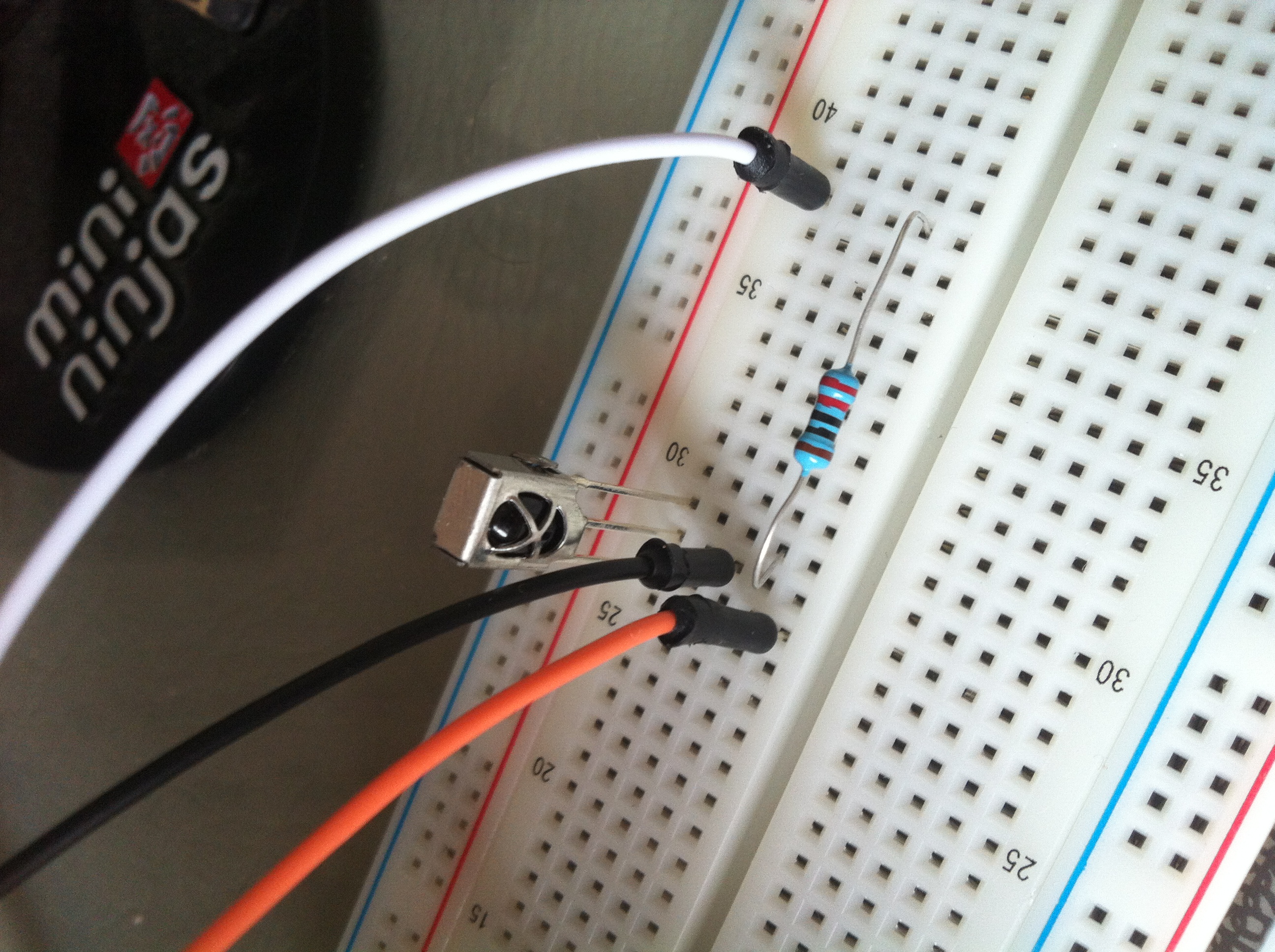
- left pin -> 11 pin of Arduino
- middle pin -> GND of Arduino
- right pin -> 220 ohm resistor -> 3.3v pin of Arduino
In the source code of snake, A0 pin is used instead 11 pin.
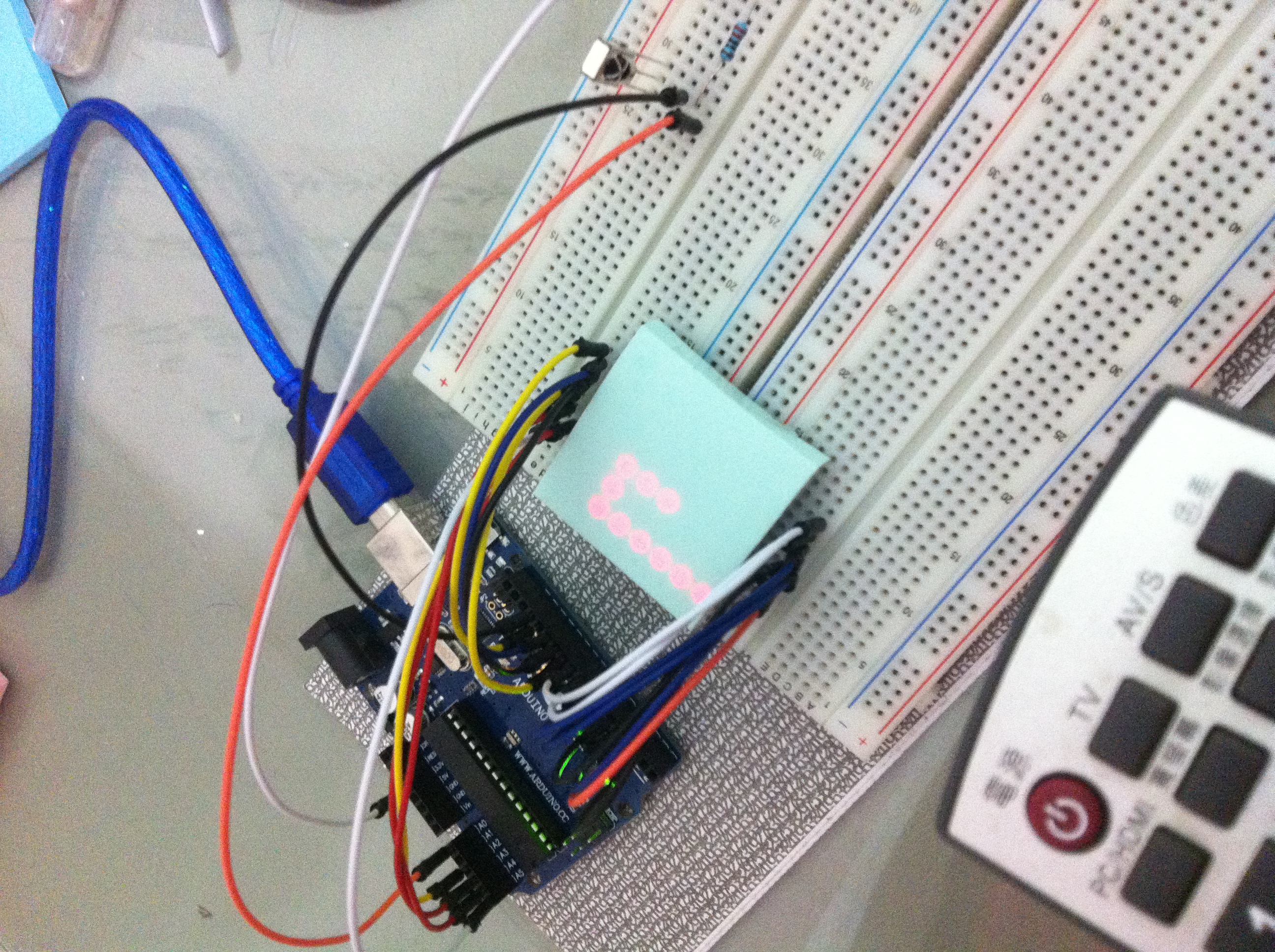
8x8 LED Matrix
Play the Row Column Scanning example, I have not run this example but connect the circuit as it.
To light up a LED, we have to connect it to a HIGH pin and a LOW pin. But there are only 16 pins on the 8x8 LED matrix which has only 2^16 combinations. To simulate 2^64 combinations, we have to do something like PWM. For example, if we want to light up LED in (1, 1), set pin of 1st row to HIGH and set pin of 1st column to LOW can tuen on the LED. In each loop, we turn on and off the LEDs.
The Refresh method is used to display the game on the LED matrix. In order to make the display stable, we need a stable refresh rate in this method. In other words, to display a pattern stablely, we must spend the same time period on each loop and LED. That’s why I turn off some LEDs twice (set a pin to HIGH twice).
void Refresh() {
int row, col, msk;
for (row = 0; row < 8; ++row) {
msk = this->masks[row];
digitalWrite(SnakeBoard::ROW[row], HIGH);
for (col = 0; col < 8; ++col) {
if (msk & (1 << col)) {
digitalWrite(SnakeBoard::COL[col], LOW);
digitalWrite(SnakeBoard::COL[col], HIGH);
} else {
digitalWrite(SnakeBoard::COL[col], HIGH);
digitalWrite(SnakeBoard::COL[col], HIGH);
}
}
digitalWrite(ROW[row], LOW);
}
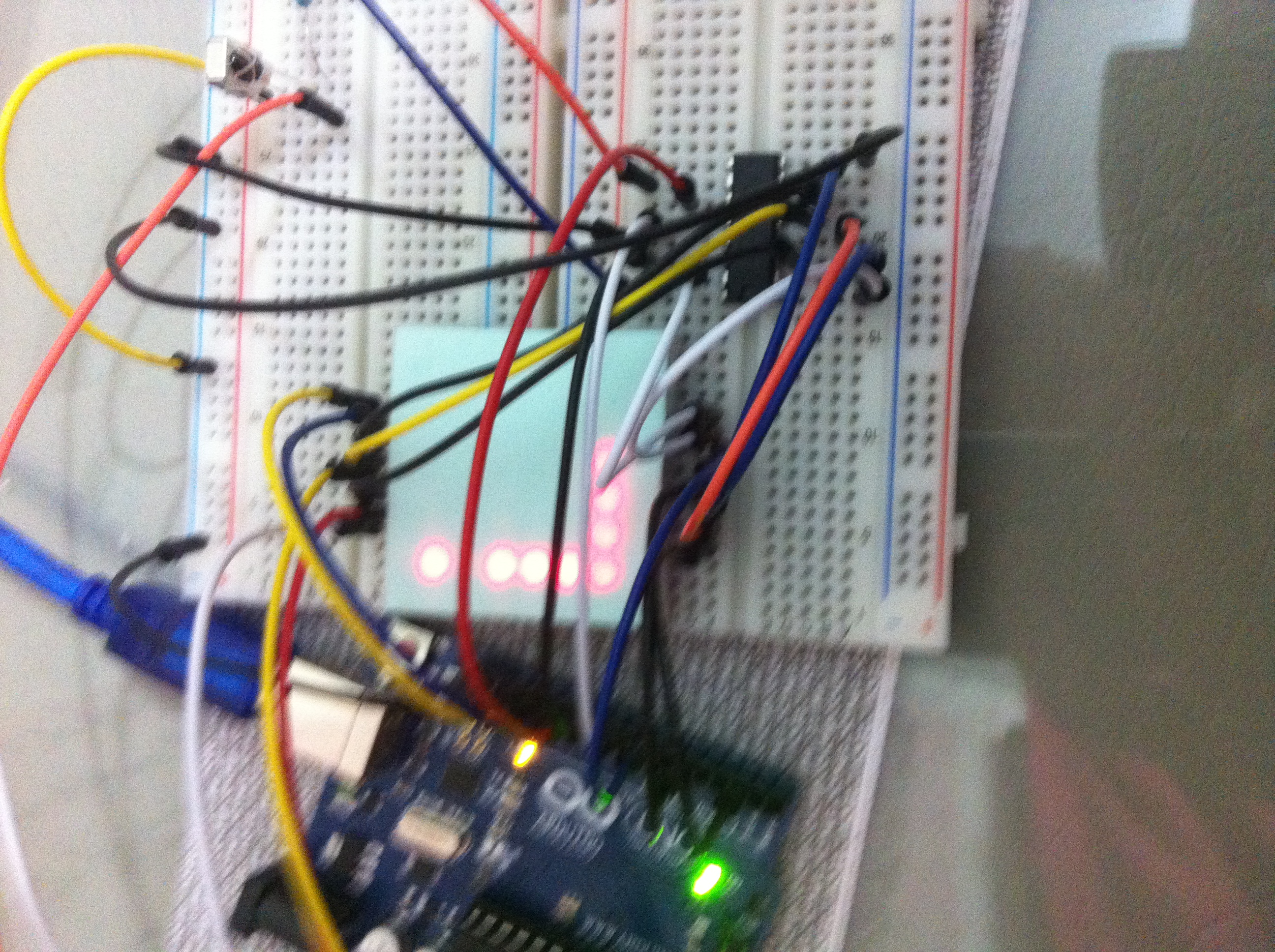
}The Final Result
To run the source code, you have to define the singals from infrared sensor. You can find the correct value by running the ‘IRremote’ example.
Now we can combine a circuit from ‘IRremote’ and ‘Row Column Scanning’ example. Remember to change the data pin of infrared sensor from 11 to A0. Then upload the snake to Arduino and start to play!
#define REMOTE_UP               (0x85AEFD19)
#define REMOTE_DOWN             (0xB66D73CD)
#define REMOTE_RIGHT            (0x5C5C901D)
#define REMOTE_LEFT             (0x8F890759)
Update 20141127
Reconnect all column pins of the LED matrix to a 74HC595 chip (because I have only one in hand :)). Refresh method become:
void Refresh() {
  for (int row = 0; row < 8; ++row) {
    digitalWrite(SnakeBoard::ROW[row], HIGH);

    digitalWrite(PIN_SIFTING_OUT_LATCH, LOW);
    shiftOut(
      PIN_SIFTING_DATA,
      PIN_SIFTING_CLOCK,
      LSBFIRST,
      ~(unsigned char)this->masks[row]);
    digitalWrite(PIN_SIFTING_OUT_LATCH, HIGH);

    digitalWrite(PIN_SIFTING_OUT_LATCH, LOW);
    shiftOut(PIN_SIFTING_DATA, PIN_SIFTING_CLOCK, MSBFIRST, 255);
    digitalWrite(PIN_SIFTING_OUT_LATCH, HIGH);

    digitalWrite(ROW[row], LOW);
  }
}